SuperDARN Radar Hardware
Transmitting
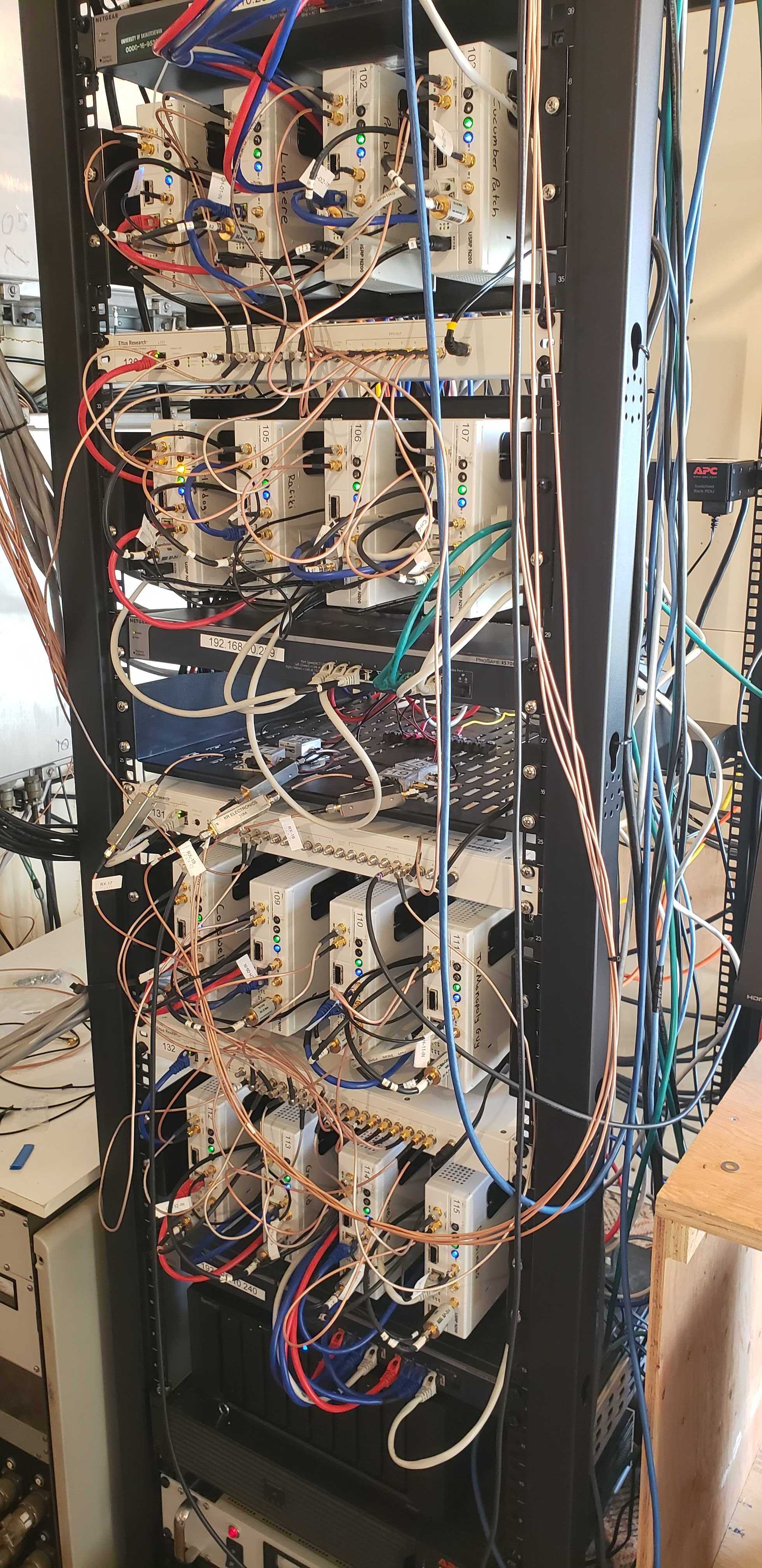
The Borealis 'rack' for the Saskatoon radar before deployment. The 16 'N200's' can be seen in rows of four.
SuperDARN radars use solid state transmitters rather than klystrons. Solid state transmitters use a lower power to transmit, and operates on a lower voltage. Benefits to using solid state transmitters for SuperDARN include a longer lifetime than klystrons, which will need regular replacement of parts. This is beneficial as many SuperDARN radar sites are located in remote and hard to access sites. Solid state transmitters are also much smaller in size than vacuum tubes, multiple can be used in a fraction of the space of a single klystron.
Transistors are credited with revolutionising the world of electronics in the middle of the 20th century. The first working transistor was invented in 1947 by physicists at Bell Labs. The three inventors, John Bardeen, Walter Brattain and William Shockley won the Nobel Prize in Physics in 1956 for their device.
The solid state transmitters in SuperDARN radars are made up of transistors. A transistor is a device made from semi-conductor material. They are used in almost all electronics as amplifiers or to switch electronic signals and power. The transistor is attached to an electrical circuit, usually with three connection points. Then a voltage or current is applied to a pair of the connections, and depending on the properties of the semi-conductor material, the output power of the transistor can be higher than its input and as such can amplify the electric signal passing through it.
Additionally, the transistor can also used as an electronic switch, where in the 'on' position the transistor is acting like a normal circuit where the current is flowing freely, this is called saturation. In the 'off' position, it limits the amount of current flowing through the circuit. The ideal transistor also limits the transition between the two positions to reduce any extra detrimental effects on the electronics.
At SuperDARN Canada, we use software defined radios which produce a low power radio signal for us. We often shorten this name to the device name: N200. Inside each of these devices are a circuit of electronic components that create a digital electronic signal. This signal is then run through a series of amplifiers which increase the power of the signal. Specifically at SuperDARN Canada in our Borealis radar control system, the low power signal from the N200 gets sent to a driver amplifier, a power amplifier and then a low pass filter in turn. The power of the signal is then checked.
Then, the power of the wave is sent to a circuit called the automatic gain control circuit (AGM). This circuit adjusts the power of the wave before it gets sent to the amplifiers, ensuring that a the power of the wave after the amplifiers is set properly. When a wave is about to be sent into the ionosphere, a high power transmit/receive switch (HPTR) connects the output of the amplifiers to the antennas. A more in-depth and technical look at the components of the Borealis hardware can be found in the Borealis documentation.
Our Antennas
SuperDARN Canada uses two different antenna types. Inuvik, Rankin Inlet and Clyde River, being younger radars, all have the wire antennas. Prince George and Saskatoon have the older style of SuperDARN antennas. Both antenna types do the same job, converting the electronic signal to a radio wave and directing it into the ionosphere.
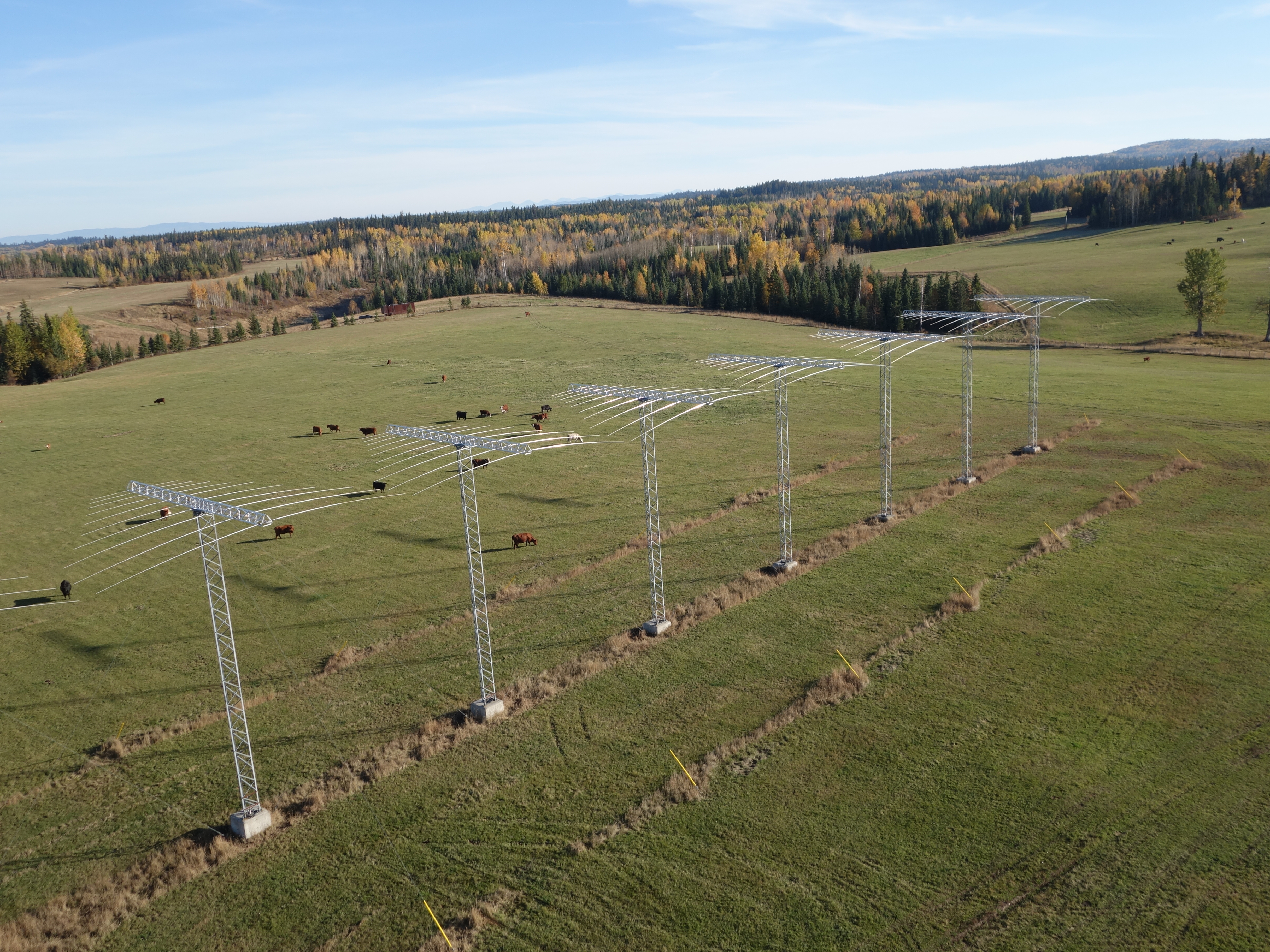
The antennas at Prince George radar in the older style.
The classic radio antenna style consist of 16 towers with a boom atop which holds a number of antenna elements along which the voltage, switching at the set frequency, forms the radio signal which propagates from the elements. See our Radio for Beginners tutorial for more information on how a radio wave is generated from an electrical current.
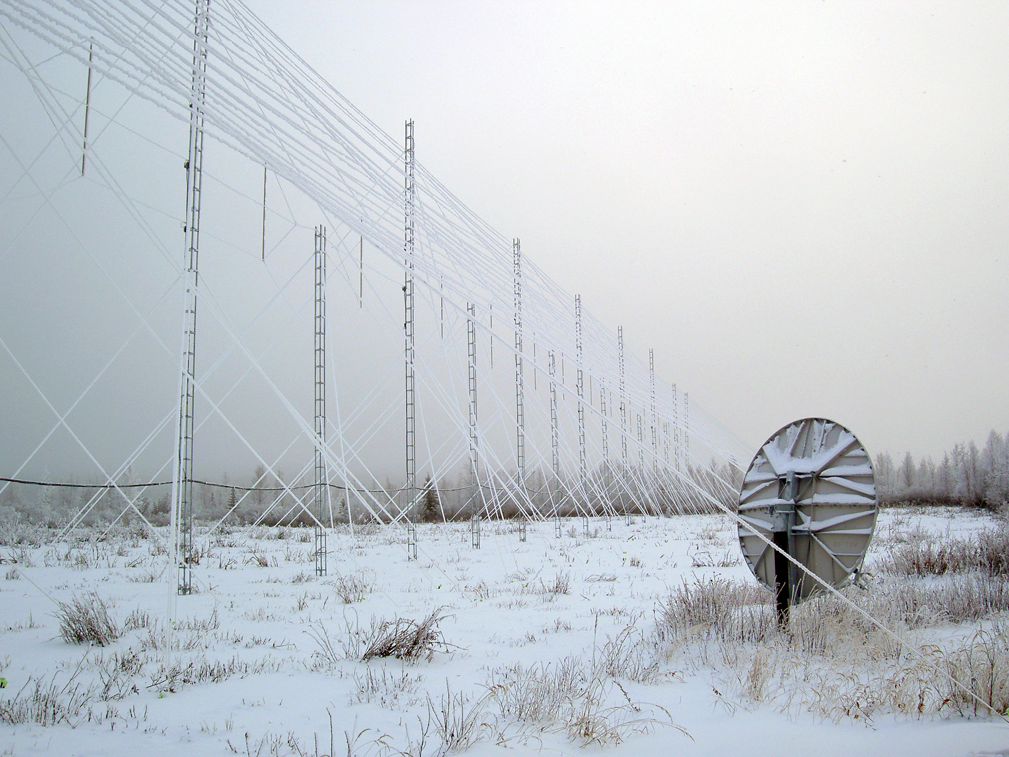
The ice laden wire antenna at Inuvik on an icy morning.
The wire antenna uses a very similar process to convert the electrical signal into a radio signal, where the wires strung between the towers act as the antenna elements. The benefits of using these newer wire antenna are that there are a lot fewer electrical connections which can fail, extending lifetime and allowing more time between repairs. There is also an added benefit where the radio signal has better 'gain', where more of the radio signal goes out of the front of the radar.
Specifically timing the signal to be transmitted from the antenna, the transmitted waves superpose into each other, allowing the signal to be strongest in a specific direction. This allows SuperDARN Canada to steer the beam of emitted radio waves into that specific direction, this is called a phased array of antennas. Changing the timings of the tranmission from each antenna allows SuperDARN Canada to build a picture of the ionosphere from 16 directions. Some other radar institutions have up to 24 beams or specific directions which they point their radar signal at.
Animation showing the ability of a phased array to direct the signal from the antennas.
Receiving
Once the signal is transmitted from the antenna into the ionosphere. The high power transmit receive switch (HPTR) switches from transmit, to receive. The radar then listens for any returning signal from the ionosphere or anything else the radio wave may come into contact with. We know that the returning signal will be have much less power and be much weaker than the transmitted signal as it has had to travel through a large area of atmosphere and ionosphere and bounce back, often bouncing off the ground too.
The antennas work in reverse, converting the radio wave into a voltage difference along the antenna elements which travels to our electronics as an electronic signal. The N200's also take in the received signal and process it. Now we have raw radio wave data from the ionosphere. To learn more about how we convert this raw data into usable scientific data, check out our tutorial From Radio Wave to Data. More information about how the ionosphere returns the radio wave can be read in our Probing the Ionosphere tutorial.
References and Further Reading
- Borealis Radar Control System Documentation
- Global Spec: Solid State Transmitters
- Explain that Stuff:Transistors