Building Radars
How to Make a Basic Radar
Every scientific radar experiment shares a few fundamental components in their set up. The experiment needs to produce the required radio frequency, and amplify it to the required power (much of the power is lost when transmitting, so a higher power means more of the signal will be received), before transmitting the wave. The wave needs to be transmitted via an antenna of some sort, and then a return signal needs to be received and analysed.
Transmitters
The Cavity Magnetron
The invention of the cavity magnetron revolutionized the field of radar science, with the newfound ability to create microwaves and radio waves with a power higher than previously achieved. The cavity magnetron generates a high power radio wave from a direct current of electricity through controlling a stream of electrons with a magnetic field. The electrons are moved between empty metal cavities in which radio waves can oscillate, not unlike the idea of resonating sound waves when you blow over the open end of a glass bottle.
It's very likely that your home microwave utilises a cavity magnetron to produce microwaves to heat up your food!
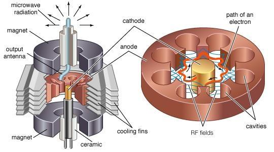
An example of a cavity magnetron from Narang & Gupta, 2015
Klystrons
Toward the middle of the 20th century, developments in electrical engineering allowed for a much higher power sources of radio waves to be achieved. Klystrons work on a very similar principle to the cavity magnetron, using cavities (completely empty volumes, even empty of air) to produce and amplify a radio wave. The difference being that the klyston has a series of cavities with various electric fields designed to bunch any electrons travelling through the klystron together - "buncher cavities".
In a klystron, electrons are injected at a constant rate, as the electrons pass through the first buncher cavity, an oscillating electric field is applied which slows down or speeds up electrons depending on what phase the oscillating electric field is at. Thus, bunching all the electrons together just like a rolling traffic-jam on a highway. Many of these cavities are lined up to amplify the "bunching" and hence amplifying the output signal from the klystron.
The final cavity, is the "catcher cavity", this cavity absorbs the energy from the electron beam that has been bunched up. The bunches of electrons that pass into this cavity create standing waves in the electric field, like resonating sound waves when you blow over the open end of a glass bottle. The electrons are decelerated by an electric field, and in decelerating they exchange their kinetic energy, to potential energy which increase the amplitude of the oscillating electric field. Hence, we should have an exact copy of the input electric field signal in the first buncher cavity, but with a much higher amplitude - our new high powered radio wave.
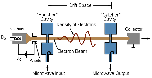
An example of a two cavity klystron. Source: Modified image based on a drawing by Christian Wolff/CC BY-SA 3.0
Solid State Transmitters
The two examples above are examples of vacuum tube transmitters, each with their own advantages and disadvantages. However, simple transistors (and various electronic components) can be combined to form a solid state transmitter, which has the benefits of being smaller, easier and cheaper to maintain, can be used for a much longer lifespan than it's counterparts and creates less noise which may interfere with returning signals.
However, the solid state transmitters are more suited to lower power experiments, and as such choice in transmitters is down to the building engineer. Solid state transmitters are mainly used in array like experiments - like here at SuperDARN, and vacuum tube transmitters are mainly used in dish-antenna systems - like that of EISCAT.
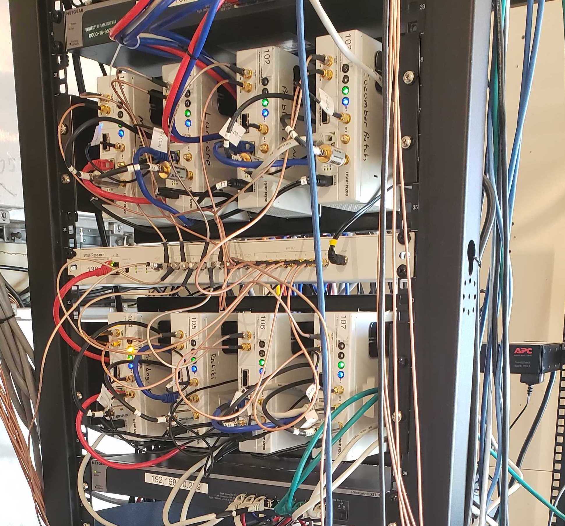
Partial set up of a SuperDARN rack, showing 8 of the 16 units containing solid state transmitters. More information on the specific set up of SuperDARN Canada radars can be found here.
Antenna
The design of an antenna is really dependant on the experiment outcome you are trying to achieve. Once a wave is generated, it will spread out in all directions, like a wave created by dropping a rock into a lake. However in science, for the most part, we want to be able to direct this wave to a target or direct it so that if we get an echo or reflection, we know where it came from. There are a number of designs found in industries, such as those at airport traffic control and ships radar tracking. However, in ionospheric science we mainly use parabolic dishes and phased array antenna.
Parabolic dish antenna are generally shaped like a large dish, these types of antenna are particularly known for being able to direct the radio wave very efficiently. It functions similar to a flashlight, in that it forms a narrow beam directed towards the area of interest. The main disadvantage of parabolic antenna, are that they need to be much much larger than the wavelength that they are transmitting, and as such are used mainly for high frequency radio waves (UHF and microwave lengths). Parabolic antenna are used for satellite communications, WAN and LAN links in data communication and in radio telescopes for astronomy.

Example of one of NASA's Deep Space Network parabolic antenna that is used to keep in touch with satellites and spacecraft as far away as Voyager 1. Credit: NASA:CalTech-JPL.
Example of a phased array 'steering' its beam by slightly offsetting the time at which each antenna transmits.
Antenna arrays, sometimes called phased antenna arrays, are a type of antenna that allows you you steer the beam of radio waves in the correct direction using electronics and multiple smaller omidirectional antennae. This also means you can steer the beam into a direction without moving the actual antenna.
By offsetting the time at which each smaller antenna transmits, you can point the beam in any desired direction as each individual beam will constructively interfere in that chosen direction (see Radar basics tutorial on superposition). A scientist can construct an array of smaller antenna to meet the needs of their specific experiment. Also important to note, is that any antenna design can be used for receiving radio signals as well as transmitting. Both antenna designs have the same benefits and downsides for receiving signals as they do for transmitting.
A very common and widely used antenna design is the Yagi antenna, designed in Japan by Yagi Uda, looks like a central boom with elements sticking out on either side. This style of antenna is commonly used in non-satellite TV broadcasts and can be found on most houses. This is very similar to the log-periodic antenna type that SuperDARN often uses in its phased arrays.
Receivers
A receiver, if not incorporated with the same transmitter and antenna to look for its own echoes, will need its own antenna to receive a signal. Just like a radio set or car radio, a receiver will receive a signal in a radio wave form. Most commonly used radio receivers use the superheterodyne principle. Read more about superhet receivers here, it is slightly beyond scope for this basic tutorial.
The basic function of a receiver is to interpret and convert the incoming wave intecepted by an antenna. The antenna will convert the waves into an alternating current which the receiver picks up and extracts the information it needs. Quite often the signal requires amplification, and using demodulation the information can be extracted from the carrier wave. A demodulator can be an electronic circuit or even a piece of software.
The word modem in networking is a shortening of modulator/demodulator, which was the primary purpose of a modem. The device extracts a data stream from a carrier signal (demodulates) which was transmitted through a telephone wire - or more recently optical fiber network - and then modulates the return wave to send information back. Modulation happens at the time of transmitting the wave, where the information that the wave needs to carry, modifies the amplitude (AM) or frequency (FM) of the wave (or in modern radio, sends 'bits' of data as '1's and '0's, or 'up' and 'down' in the wave). Demodulation is being able to read those special modifications to the wave, and hence extract the information at the receiving end.
References and Further Reading